
Simple Steps to Test Your ICM with a Multimeter
The smooth operation of a vehicle largely hinges on its ignition system, a complex network of components that ensure your engine starts and runs efficiently. Among these vital parts, the ignition control module is crucial in managing the ignition timing, directly impacting engine performance. Testing the ignition module control with a multimeter is essential for diagnosing potential issues. If this component fails, it can lead to a series of frustrating issues, including difficulty starting the engine or poor fuel efficiency.
How to test Ignition Control Module?
Understanding how to test the ignition control module effectively is essential for any car owner or hobbyist seeking to troubleshoot ignition problems. A multimeter, a versatile tool for measuring electrical properties, can help diagnose whether your ignition control module is functioning correctly. This simple process can save time and money by pinpointing the source of ignition system failures.
This article will walk you through simple steps to test your ignition control module using a multimeter, from assembling the required tools to interpreting your readings. By following our guide, you’ll gain the confidence to address potential ignition issues and maintain the overall health of your vehicle’s ignition system.
Understanding the Ignition Control Module
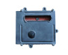
The Ignition Control Module (ICM) serves as a critical part of a vehicle’s ignition system and is tasked with precisely managing the timing of the engine’s spark plugs. When working correctly, it ensures optimal engine performance by coordinating ignition coils to fire at precisely the right time. The ICM commonly resides within the engine compartment, often found attached to the distributor housing or mounted separately, depending on the vehicle’s make and model.
Malfunctions in the ICM can lead to engine misfires, stalling, and difficulty starting the car. Symptoms of a failing ICM include irregular engine behavior and a check engine light. To ensure the ICM operates efficiently, it must have a good ground connection and remain free from electrical faults in the associated wiring. Typically, a qualified mechanic will conduct diagnostic tests using a digital multimeter to measure the ICM’s resistance specifications and to check for any bad ground or infinite readings that indicate issues.
For proper diagnosis, one needs to reference the vehicle’s repair manual for the correct wiring diagram and resistance specifications. Regular checks and maintenance are recommended to prevent unexpected engine stalling and ensure the longevity of the ICM.
Components and Functions of the Ignition Control Module
The ignition control module (ICM) is a vital component in the engine’s ignition system. It primarily controls the ignition coils, ensuring they fire at the correct time, which in turn ignites the air/fuel mixture within the cylinders. The ICM works closely with other components such as spark plugs, plug wires, and the distributor housing to maintain the precise timing needed for engine performance and efficiency.
Key Components and Functions of the ICM:
- Ignition Coils: The module receives signals to energize the ignition coils at the right moments.
- Spark Plugs: It helps in timing the release of electrical energy that the ignition coils send to the spark plugs.
- Distributor Housing: On some vehicles, the ICM may be located within the distributor, using the distributor’s mechanical timing mechanisms.
The ICM also interacts with sensors and the vehicle’s onboard computer to adjust the ignition timing for optimal performance under various operating conditions. It ensures engine reliability by preventing misfires, engine stalling, and other performance issues connected to the ignition process.
Symptoms of a Malfunctioning Ignition Control Module
When an Ignition Control Module (ICM) begins to fail, several notable symptoms may present themselves. A key indicator is engine misfires, which occur when the engine skips over one of the steps in its combustion process. This can be noticed by a rough idle or a change in the engine’s rhythm.
Another symptom is issues with starting the car. A faulty ICM can prevent the ignition coils from receiving the proper signals, leading to difficulties when turning the ignition key in the engine compartment. Similarly, the car may stall unexpectedly during operation due to the erratic supply of sparks from the spark plugs.
Drivers might also notice a reduction in fuel efficiency. When the ICM fails, the precise timing required for optimal combustion is disrupted, causing the engine to consume more fuel.
Lastly, the car might fail to start. When the ICM does not function at all, it prevents the ignition coils from providing the necessary spark to ignite the fuel, and as a result, the engine will not start.
Recognizing these symptoms early and consulting with a qualified mechanic can prevent potential further damage to the vehicle’s ignition system.
Necessary Tools for Testing
To test an Ignition Control Module with a multimeter, you will need the following tools:
- A digital multimeter capable of measuring battery voltage, resistance, and, if possible, dwell angle.
- Piercing probes are used to make contact with the wiring of the ignition control module connector without causing damage.
- A copy of your vehicle’s repair manual with the wiring diagram and resistance specifications for the ICM.
- Basic hand tools such as screwdrivers or sockets may be required to access the ignition control module.
- A clean cloth and contact cleaner to ensure a good connection when measuring.
- A notebook and pen are needed to record your findings during the test.
If you are uncertain about the testing process or the interpretation of results using these tools, it is advisable to seek professional assistance.
Safety Measures Before You Start
Before beginning any tests on your vehicle’s ignition control module with a multimeter, it is crucial to follow these safety measures to prevent accidents and damage to your vehicle’s electrical system:
- Vehicle Preparation: Ensure the car is parked on a level surface, and the ignition key is in the “off” position. This avoids any unintended engine starts.
- Battery Caution: Disconnect the negative terminal of the car’s battery to prevent electric shock or short circuits. This is particularly important when working around the engine compartment.
- Engine Cool Down: If the vehicle has been running, allow the engine to cool down before starting the tests to avoid burns.
- Personal Safety: Wear protective gear, such as safety glasses and gloves, to protect against accidental sparks that might occur when testing the ignition modules or wires.
- Secure Surroundings: Remove any flammable materials from the work area, and ensure the work environment is well-ventilated.
- Proper Tools: Use tools with insulated handles, including the multimeter and piercing probes, to maintain a safe barrier between you and any electrical components.
- Reference Material: Have the vehicle’s repair manual on hand for wiring diagrams and resistance specifications. This ensures the tests are conducted accurately.
- Qualified Assistance: If you feel uncomfortable or unsure at any point, it is recommended that you consult with a qualified mechanic.
Step-by-Step Guide to Testing with a Multimeter
To begin testing an ignition control module with the multimeter, set up your multimeter correctly. First, switch it to the appropriate measurement setting. If you’re uncertain about which setting to use, consult the vehicle’s repair manual for specific instructions related to your car’s ignition system. Typically, you will set the multimeter to measure DC voltage for voltage testing; for resistance testing, you will set it to the ohmmeter function. Ensure the test leads are connected properly: red lead to the positive terminal, black lead to the negative terminal, or a metal surface serving as ground.
Performing the Initial Check
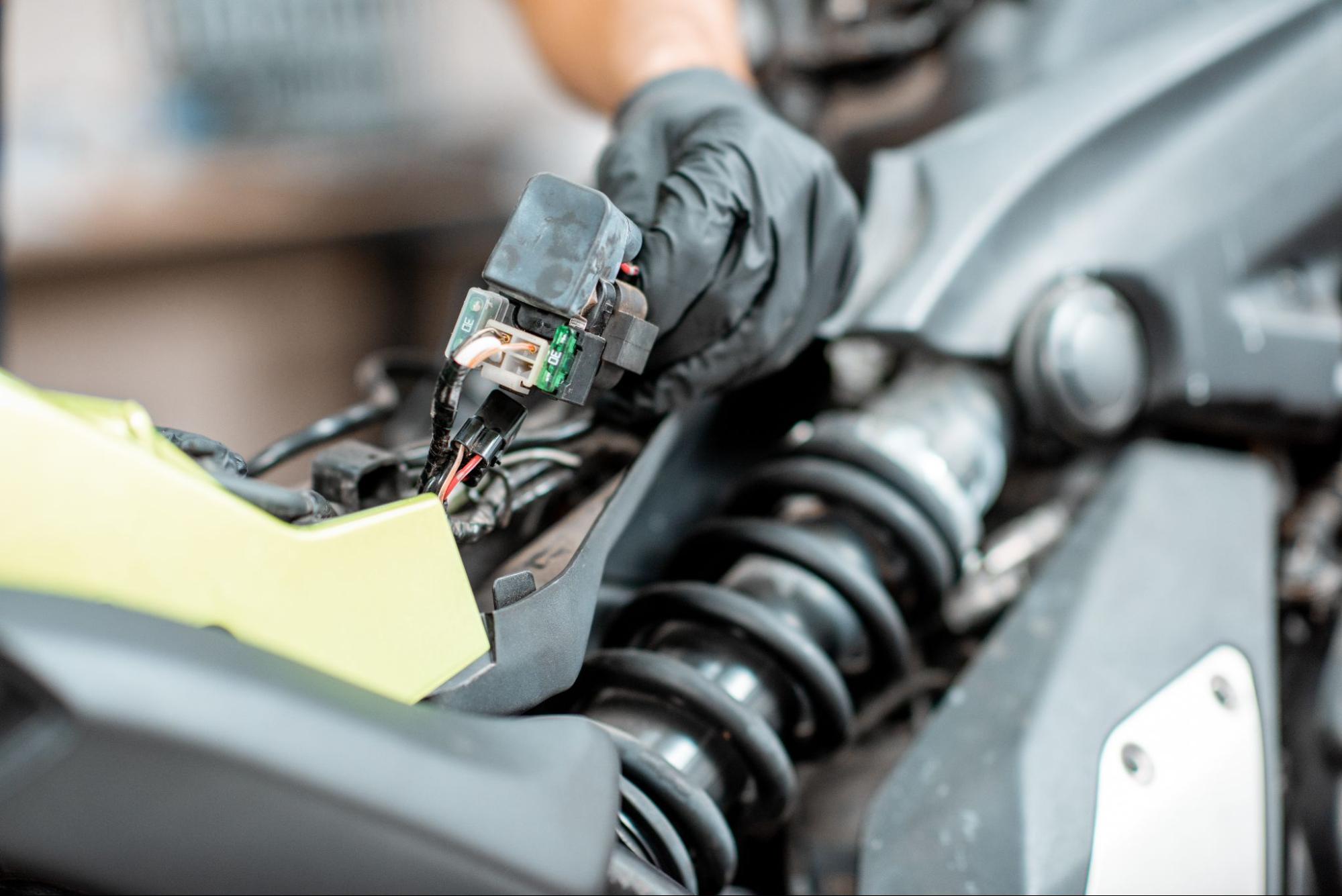
Before actively using the multimeter on your ignition control module, examine the ignition system. Check the physical condition of the module, wiring, and associated components like the distributor housing and ignition coils. Look for visible signs of wear, damage, or bad ground connections. Ensure all connectors are secure. A visual check can often reveal basic issues that cause engine misfires or stalling without needing to resort to more complex testing.
Measuring Voltage Output
To measure the voltage of the ignition control module, locate the module’s battery voltage supply wire; the repair manual or a wiring diagram will help with identification. Once located, reconnect the negative terminal of your battery, turn the ignition key to the “on” position without starting the engine, and place the multimeter’s negative lead on good ground. Touch the positive lead to the module’s power input wire. A healthy module should display battery voltage. If the voltage is significantly lower, it can indicate a problem with the power supply to the module.
Testing Resistance Levels
Testing the resistance levels of the ignition control module is important for identifying underlying issues that can lead to engine misfires or stalling. To start, disconnect the ignition control module connector and all related ignition coils to ensure safety. Using the multimeter’s ohmmeter function, measure the resistance across the specified terminals of the ignition module (as indicated in the repair manual). Compare the readings to the resistance specifications provided in the manual; discrepancies can point toward a faulty module. If the multimeter shows an infinite reading, there may be an open circuit.
In resistance testing, it’s also crucial to check the ignition wires, including plug wires and spark plug wires. The integrity of these connections significantly affects the precise timing of the ignition system.
During your diagnostics, use the reference material to interpret your findings correctly. If the module is proven to be working inconsistently or not at all, and you’re experiencing symptoms like engine stalling or engine misfires, you might be dealing with a bad ignition coil or module. Remember, while these straightforward tests can be conducted by oneself, consulting a qualified mechanic is always advisable for precise diagnosis and repairs.
Setting Up Your Multimeter
When preparing to test an ignition control module with a multimeter, correctly setting up your digital multimeter is pivotal to obtaining accurate readings. Here is a step-by-step guide to setting up your multimeter:
- Ensure the multimeter is switched off before connecting any probes.
- Identify the multimeter’s leads: the common (COM) lead is typically black, and the voltage/ohm lead is usually red.
- Insert the black lead into the COM port and the red lead into the port marked for ohm (Ω) measurement as you will be testing resistance for most ignition module tests.
- Switch on the multimeter and set it to the appropriate ohms (Ω) range according to your repair manual’s resistance specifications. If uncertain, start with a higher range to protect the multimeter from damage.
- Inspect your probes to ensure they are not damaged and are suitable for the test. Piercing probes could be needed if you must penetrate insulation on wires.
- Adjust the multimeter to the appropriate voltage setting if intending to measure voltage.
- Confirm the multimeter’s display is operational and ready for testing.
By following these steps, your multimeter will be suitably prepared for use when testing your ignition control module.
Common Ignition Issues Beyond the Control Module
Common ignition issues can arise beyond the control module and potentially cause similar symptoms. It’s important to diagnose them correctly to avoid unnecessary replacements and costs.
Key components prone to malfunctions:
- Ignition Coils: Responsible for converting battery voltage to a high voltage to ignite the spark plugs. A bad ignition coil can lead to engine misfires and stalling.
- Spark Plugs: These components ignite the air/fuel mixture in the combustion chamber. Worn or fouled spark plugs may cause misfires or poor engine performance.
- Ignition Wires (Plug Wires): Faulty ignition wires may interrupt the electrical connection between the ignition coils and spark plugs, resulting in engine misfires.
- Distributor Housing: Cracks or wear in distributor housings can cause ignition issues in vehicles with a distributor, disrupting the precise timing needed for optimal engine performance.
- Battery Voltage: Low battery voltage can affect the ignition system’s performance, leading to difficulties in starting the engine or engine stalling.
- Bad Ground Connection: A poor ground connection can result in an unreliable electrical system, which might affect the ignition system’s efficacy.
For proper diagnosis, consult a repair manual for specific resistance specifications and use a digital multimeter for accuracy. For complex issues, always consider seeking the expertise of a qualified mechanic.
Testing Methods for Different Ignition Systems
When it comes to testing the ignition control module (ICM), it’s important to note that different types of ignition systems may require specific testing methods. Traditional ignition systems with a distributor, those with distributor-less ignition systems (DIS), and coil-on-plug (COP) systems each have unique configurations and components. Consequently, when preparing to test the ICM, it’s critical to first identify which type of ignition system your vehicle possesses and understand the corresponding testing procedures.
Testing generally involves using a digital multimeter to measure resistance, continuity, and in some cases, the signal output of the ignition module. Before beginning any testing, one should always disconnect the battery to prevent accidental shorts, refer to the vehicle’s wiring diagram for the correct pin identification, and ensure the multimeter is set to the correct measurement scale. Safety should be a priority, so ensure that you work in a well-ventilated area and follow all precautions outlined in the vehicle’s repair manual.
For distributor ignition systems, checking connections at the distributor housing and ensuring clean contacts can be part of the process. With DIS and COP systems, you may focus on the individual coils and their primary and secondary circuits. Always ground the multimeter’s negative lead on a clean metal surface of the engine compartment to ensure accurate readings.
Testing HEI Modules
Testing a High-Energy Ignition (HEI) module, often found in older vehicles with a distributor, involves a few specific steps. First, locate the ignition module, which typically sits within the distributor housing. Disconnect the module’s connector and inspect it for any signs of corrosion or damage. Use a digital multimeter to check for continuity between the module’s power terminal and the positive battery terminal, ensuring that the HEI module is receiving power.
Next, switch your multimeter to the diode test or resistance test setting. Consult the repair manual for proper resistance specifications, connect the test leads to the corresponding pins as directed by the manual, and look for readings that match the specified ranges. An infinite reading or one that significantly deviates from the expected value may indicate a faulty HEI module.
Testing Ignition Coils
Ignition coils are critical for transforming the battery’s low voltage into the thousands of volts needed to create a spark in the spark plugs. To test an ignition coil, first ensure the engine is off and locate the ignition coil – remember that some vehicles may have multiple coils. Remove the spark plug wire from the coil and use a multimeter to check resistance across the primary and secondary windings of the coil.
The primary winding is usually tested by placing the multimeter leads on the positive and negative terminals of the coil. Find the secondary winding’s resistance by placing one lead on the coil’s output tower (where the spark plug wire connects) and the other on the coil’s positive terminal. The exact numbers for ideal resistance can vary, so cross-reference your readings with the specifications in your repair manual.
Abnormal resistance levels or a complete lack of continuity can signify a bad ignition coil. If you identify a bad coil, it must be replaced to ensure optimal engine function since a faulty coil can lead to engine misfires and poor performance.
Lastly, it’s good practice to inspect all related connectors and wiring, such as the ignition coil connector, for damage or corrosion, which could affect the performance of the coil. If after testing, the results are inconclusive or you don’t feel confident in your diagnosis, consulting a qualified mechanic is always advised.
By following this guide, you can ensure that your ignition control module is functioning correctly, which will help maintain your vehicle’s performance and reliability. If you encounter any difficulties or need professional assistance, don’t hesitate to contact us or visit our website or blog to learn more about our services and how we can help you keep your vehicle running smoothly.
Remember, precise timing and proper connections are crucial for the ignition system, and a malfunctioning module can severely affect engine performance.